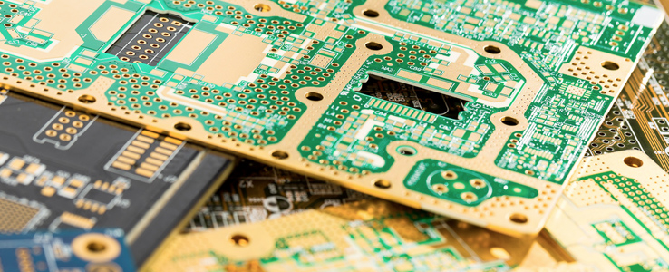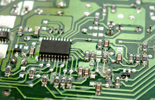

So, let’s get started with What is MultiLayer PCB? You should also have a look at the JLCPCB Multilayer Fabrication services. Let’s first have a look at the definition of PCB: PCB is an abbreviation of the printed circuit board, comes with different copper conductive paths, traces & lines, incorporated on a single board to electrically connect different electronic components. We have seen single-sided PCB and double-sided PCB in our previous posts, so go through them first. Today, I am going to give you a detailed overview of Multilayer PCB, where we will cover what is Multilayer PCB? & why do we need to use it? We will also discuss its Construction, advantages, disadvantages, etc.

Works for CAN bus, LINbus and Modbus protocols.Hello Friends! I hope you all are well. BUS PCB: It supports the same features as the IC PCB.Integrated Controller): Has an H-bridge for a wide range of configurable feedback outputs and performance settings, as well as monitoring and parallel drive Simple PCB: Runs the actuator in and out, including endstop outputs and a few feedback options.Three types of PCBs for LINAK industrial actuators
#WHAT IS PCB FREE#
Polarity protection ensures that the actuator is not damaged in case the power supply wires are wrongly connected.Īny questions about PCBs for industrial electric linear actuators, please feel free to contact your local LINAK office. If a voltage peak passes this level, the PCB will be shut off. The load dump level for LINAK industrial actuators is predefined to 45 volts.

Sensors monitor both the H-bridge temperature and the ambient temperature inside the actuator housing and stop operation before the heat reaches damaging levels.įor EMC protection the actuator PCB has a load dump functionality and a polarity protection. A microcontroller measures the current flowing through the H-bridge, and it shuts off the power if the current exceeds a predefined level. Measuring current and temperature protects the PCB’s electronics and helps ensure reliable actuator performance. This function is controlled by ramping up a PWM Motor Control signal and works in the same way as gradually releasing the clutch in a car. A heartbeat signal ensures the electronics are working properly, and the soft start/soft stop feature reduces the mechanical stress on the machinery and the actuator. For maximum self-locking ability on your actuator, the motor should be shorted when not moving.Ī number of PCB features help protect the machinery, running with a LINAK industrial actuator. These transistors replace the functionality of mechanical switches/relays. The heart of our integrated controller is an H-bridge, which simply controls the in/out movement of an actuator by activating two transistors to make current flow diagonally past the motor connection. The physical position of a PCB controlled linear actuator is based on Hall effect sensors, counting the number of pulses per spindle revolution. One of the most important things to know about an actuator is its position.

Our man Hunter Stephenson explains all essentials in this video. Know more about EMC (electromagnetic compatibility) protection and the basic functionality of an H-bridge. How current and temperature measurement can protect the actuator and the industrial machinery in which it is mounted. Learn how positioning and soft start and stop of an actuator is controlled.


 0 kommentar(er)
